
|
|
| | Home | Products | Tools | Downloads | Contacts | | |
|---|---|
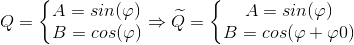
Position encoders with quadrature output signal are used in many applications. The quality of quadrature signal and it parameters have direct impact on measurement accuracy and control algorithms of end system.
Typically for increasing of resolution, quadrature signal interpolators based on atan function are used. Therefore the most critical error is an additional phase shift between components A and B (φ0).
It can be caused by wrong adjustment of the sensor, or misalignments in signal measurement path, and is manifested in the influence of one component to another. It means that one component contains part of other orthogonal component.

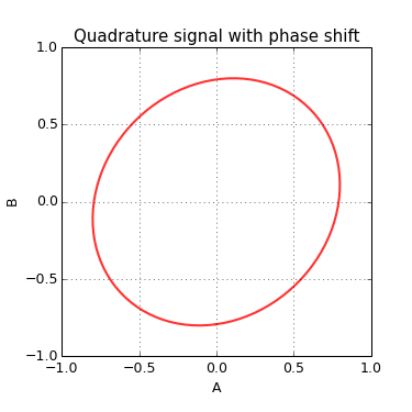
The wrong component should be removed to get back the right original signal. From this point of view it is possible to subtract an error part from one component and reconstruct the original quadrature signal.
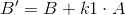
k1 - Phase correction coefficient
This operation changes the amplitude of quadrature signal, which should also be corrected.
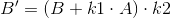
k2 - Amplitude correction coefficient
The coefficients k1 and k2 can be calculated as:
In practice it is not possible to determinate which signal is wrong. Also components of quadrature signal have limited signal to noise ratio, and correction is only one component may worsen this ratio. For this reason it is more optimal to correct both symmetrically.

This phase correction method well suited for embedded applications where processor resources and processing time are especial critical.
C code for phase correction based on floating point operations:
alpha = (qa + qb * k1) * k2;
beta = (qb + qa * k1) * k2;
Fixed point representation with 15 bit fractional part:
alpha = (s16)((((s32)qa + (((s32)qb * k1) >> 15)) * k2) >> 14);
beta = (s16)((((s32)qb + (((s32)qa * k1) >> 15)) * k2) >> 14);Here is represent of correction result of real quadrature signal from magnetic rotary encoder. The encoder has mount misalignment that caused additional phase shift about 9 degrees.
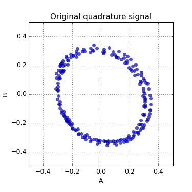
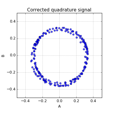
The Python script for demonstration of correction algorithm can be found here: qphase.py